
Overcoming Hard Geological Static Pressure Pile Planting Construction Technology


▍Abstract
Abstract:The main pier cap of Erdao Songhuajiang extra-large bridge of ZT07 Section ofHegang-Dalian Expressway was in a complex geological and hydrologicalenvironment. Combined with cap construction and through scheme comparison, thesteel sheet pile cofferdam was built using static pressure pilingtechnology. Theauthor analyzed and compared static pressure piling technology and traditionalconstruction technology, and elaborated and summed up the former's constructionprinciple, technological process, operation essentials and implementationeffect to offer references to similar projects.
Dalian HydraulicPile Driver Machinery & Technology Co., Ltd
Manager Xiang, thank you for your dedicationto the pile project. The author deeply studied the application advantages ofstatic pressure pile driver twist drill aided mode in the pebble bed, whichoffered a great reference value to similar geological engineering. Related datain this paper also offered a great reference value to equipment upgrade andtransformation of manufacturers!
▍1 Project Overview
Erdao Songhuajiang extra- large bridge of ZT07 Section ofHegang- Dalian Expressway undertaken by CCCC First Harbor Engineering CompanyLtd. 3rd Company has an overall length of 1260m and a structuralstyle of 66m+120m+66m three- span variable cross- section prestressed concretecontinuous steel structure. The main bridgecrosses Erdao Songhua River, and main pier caps 11# and 12# are on the floodland on both sides of the main river channel.
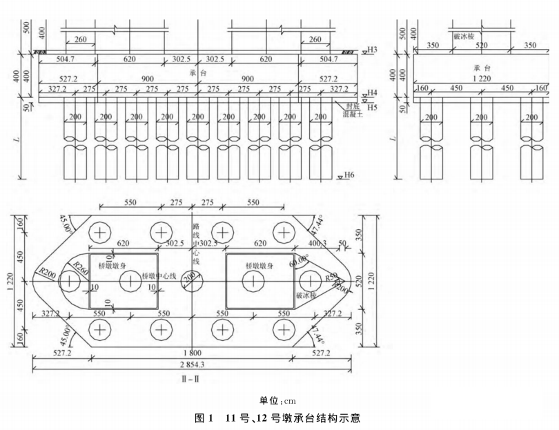
The dimensions of main pier caps 11# and 12# are 28.54m (length)x 12.2m (width) x4m (thickness), a 50cm thick concrete cushion is below thecap, and there is an arc on both sides of the cap. The bottom elevation of the pier cap 11# is 420.81m andthe top elevation is 424 81m; the bottom elevation of the pier cap 12# is422.01m and the top elevation is 426.01m. The designconcrete consumption is 1169.2m?. The specificdimension is shown in Fig. 1.
1.1 Engineering Hydrology
 “
“
The river channel at the bridge location has a "U"section, the water level elevation of the main river channel in a normal yearis 426- 428m (higher than the top elevation of the cap), the water width isabout 100m, the largest river in the bridge site is Erdao Songhua River, andtwo brooks flow to Erdao Songhua River via Xiaozhuanghao in the bridge site. It is mainly supplied by numerous unequal- sized mountainrivers in the Changbai Mountain region, and the flow changes greatly withseason.
1.2 Engineering Geology
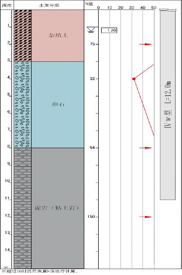
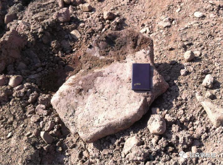
The bridge is located in the Erdao Songhua River section ofBeishuitan Basin. The bridge islocated in an area high on both ends and broad and flat in the middle. The area where thecap is located is covered with 6 9m thick gravel and pebble bed, with pebblesize of 2- 8cm and even up to 18cm, sub- circular shape, pebble content of above70%, medium- coarse sand as main packing, strong water permeability and instability;there is intensely weathered silty mudstone 9- 32m below the surface, withpartly damaged undisturbed structure, arenopelitic structure and disintegrationin water.
1.3 Site Conditions for CapConstruction
(1) foundation construction, the pier caps 11#and12# are backfilled with clay until the elevation reaches 428m.(2) The cap construction period is 6-8 months, which will beaffected by flood in rainy and flood seasons.
▍2 Construction SchemeComparison
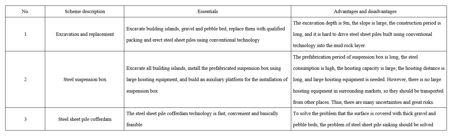
This super large bridge is one of two key control projects of 11sections with a tight schedule. Due to complex hydrogeological condition ofcap, it is crucial to determine reasonable supporting technology Theconstruction schemes are compared as shown in Table 1 and the steel sheet pilecofferdam scheme is selected ultimately.
Dalian HydraulicPile Driver Machinery & Technology Co., Ltd
When constructing steel sheet piles at thepebble bed, China Railway Group applied two relevant patents, "Aconstruction method for waterproof curtain lead hole of steel sheet pile atpebble bed" and "A construction method for steel sheet pile cofferdamat deep pebble bed", which can drive steel sheet piles at the pebble bed.As far as I know, the static pressure pile driver has certain advantages inimproving the construction and economical efficiency and reduce damage tosurrounding stratum.
A construction method forwaterproof curtain lead hole of steel sheet pile at pebble bed
From (www.zhangqiaokeyan.com Likes: 0 Views: 16
Application date: September 24, 2022 00:00:00
Publication/announcement No.: CN202211170985.3
Publication/announcement date: December 9, 2022 00:00:00
Applicant (patentee): China Railway Guangzhou Engineering GroupCo., Ltd. 2nd Engineering Co., Ltd.; China Railway GuangzhouEngineering Group Co., Ltd.
Inventors: Tang Jun, Feng Zhirong, Zhou Xiong, Wei Chuang, Tang Dayong, XieYongfa, Li Hua, Ban Wenhu
Abstract: This application disclosed a construction method forwaterproof curtain lead hole of steel sheet pile at pebble bed and relates tosteel sheet pile waterproof curtain construction period, including thefollowing steps: Step 1: Form several reserved holes in the pebble bed usinglead hole equipment continuously in the layout direction of steel sheet pilesand connect two adjacent reserved holes; step 2: Fill the reserved holes withclay to lay a foundation for steel sheet pile construction; step 3: Erect steelsheet piles with a certain space from the pile bottom to the pebble bed; step4: Repeat steps 1-3 until the steel sheet pile waterproof curtain is formed.This application can lay a foundation for steel sheet pile construction throughfilling the reserved holes with clay, avoid damage to steel sheet piles causedby collision with the pebble bed in the construction process and ensure normalconstruction of steel sheet pile waterproof curtain in the pebble bed
A construction method forsteel sheet pile cofferdam at deep pebble bed
Data source: www.zhangqiaokeyan.com Likes: 0 Views: 18
Application (patent) No.: CN202210992917.9
Application date: August 18, 2022 00:00:00
Publication/announcement No.: CN202210992917.9
Publication/announcement date: October 4, 2022 00:00:00
Applicant (patentee): China Railway No.5 Engineering Group 1stEngineering Co., Ltd.; Ningxia Communications Investment EngineeringConstruction Management Co., Ltd.; China Railway No.5 Engineering Group Co.,Ltd.
Inventors: Wang Jinguo, Cong Pei, Liu Yunlong, Cui Jia, Tang Yu, DongXingbing, Liu Huaping, Wang Manfuqian, Peng Xuejun, Ling Tao, Lu Xin, TianZhongchu
Abstract: This invention relates to a construction method forsteel sheet pile cofferdam at deep pebble bed S1: Drill holes in the cofferdam;S2: Build steel beams in the bored piles, pave steel sheets and form aplatform; S3: Build the guide frame of steel sheets; S4: Drive steel sheetpiles; S5: Pump water in the cofferdam, excavate and install the supports inthe cofferdam layer by layer; S6: Build the cap and the pier body; S7: Removeinternal supports; S8: Remove steel sheets; before each steel sheet pile in S4is driven, drill holes in the middle of steel sheet piles and correspondingposition of the latch to form lead holes, weld water pipes in the position ofcorresponding lead holes for high pressure water injection in the pilingprocess, in order that pebbles in and around the lead holes float with highpressure water and steel sheet piles pass smoothly
Data source:Network In case of infringement, please contact for deletion
▍3Structural Design of Steel Sheet Pile Cofferdam
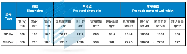
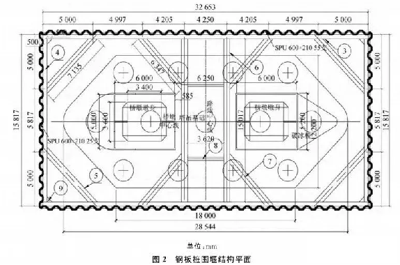
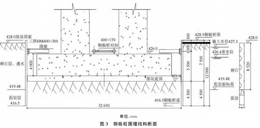
Rectangularcofferdam is adopted, the length of steel sheet pile is 12m, the steel sheetpile passes through the pebble bed and the mudstone for 2m, the top elevationof steel sheet pile is 428.5m, which is higher than the normal water levelelevation. In the initial design period, hot-rolled SP-IIw steel sheet pile(width: 600mm, height: 130mm,wall thickness: 10.3mm) is adopted. After passingthe process test, SP- IVw steel sheet pile (width: 600mm, height: 210mm, wallthickness: 18mm) is adopted; there are 2 internal supporting layers in theinitial design period and 1 layer after optimization, as shown in Fig. 2 andFig. 3.
4 Selection of Steel SheetPile Sinking Process
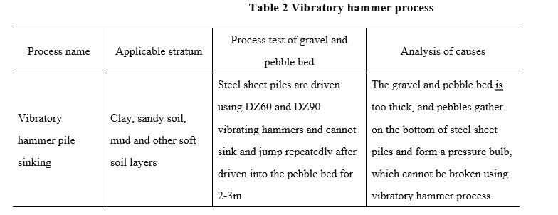
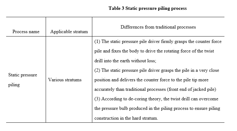
Traditional vibratory hammer process and static pressure pilingprocess are compared, as shown in Table 2 and Table 3.
▍5 KeyStatic Pressure Piling Technologies
5.1 Principle of StaticPressure Piling Process of Steel Sheet Piles
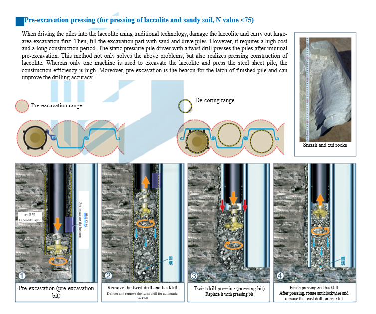
According to hardness of stratum, static pressure piling processincludes independent pressing process, water jet pressing process, and twistdrill pressing process (namely hard stratum construction process). Twist drillpressing process is adopted for main pier cap construction of extra-largebridge
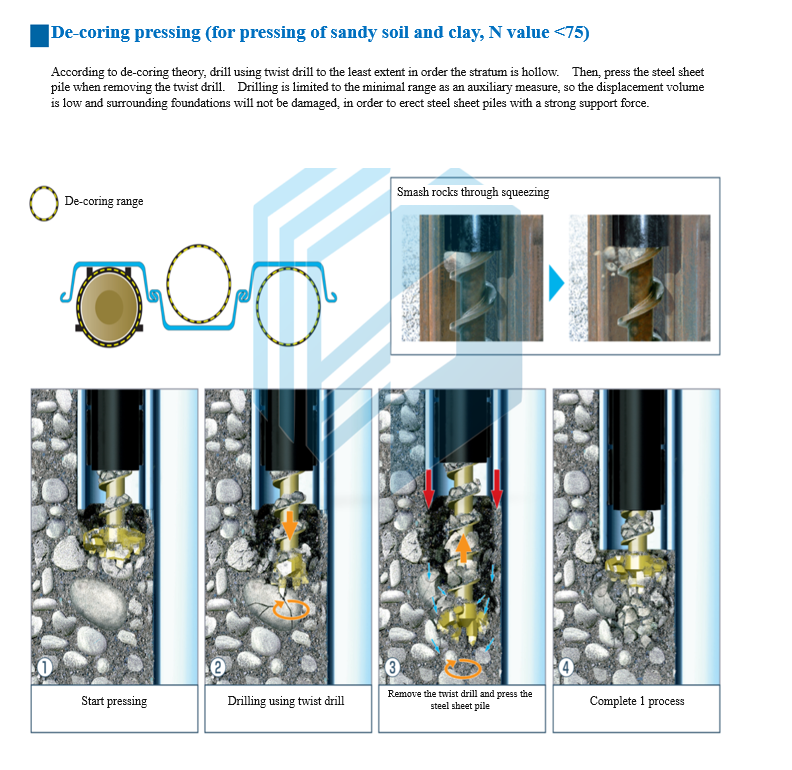
Principle of twist drill of static pressure pile driver
According to static pressure pile driver and twist drillpressing process, in a hard stratum, the pile is pressed and drilled usingtwist drill according to "de- coring theory" to reduce the penetrationresistance and finish pressing construction. It is applicable to mudstone, gravel, granite and othersoft and moderately hard rock stratums.
The static pressure pile driver grasps many jacked piles anddrives them into the earth as a whole. It uses the pull-out resistance as the counter force toapply a static load to the next pile. Without vibration and noise, drive thepile into the earth and form a pressure bulb at the front end of the pile. In ahard stratum, the pressure bulb should be broken using twist drill to continuewith pressing.
5.2 Main Technical Features
(1) Determine piling parameters through process test beforeformal construction.
(2) Select piling method according to geological condition.
(3) Inflate high pressure air in the pre-excavation process toimprove the pre-excavation efficiency.
(4) To prevent seepage path at the pile tip caused bydisturbance of twist drill, the last 50cm of the pile should be pressed to thedesign elevation .
(5) When erecting the corner pile, adopt different pilingmethods according to the direction of the last steel sheet pile.
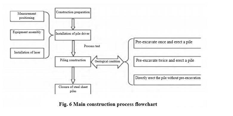
5.3 Main ConstructionProcess
The main construction process flowchart is shown in Fig. 6.
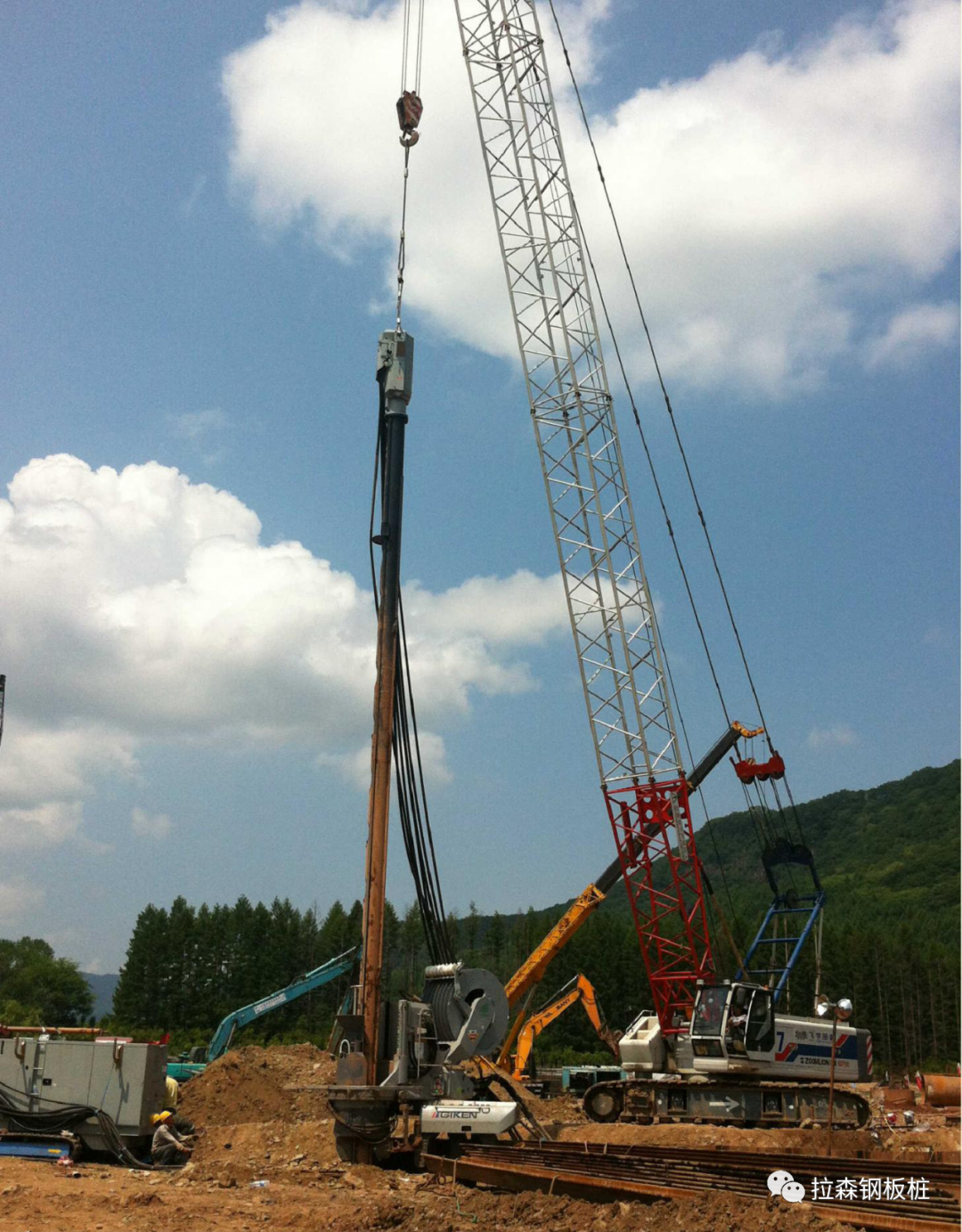
5.4 Composition of StaticPressure Piling Equipment
The static pressure piling equipment consists of the power unit,the static pressure pile driver and the steel sheet pile crane. As shown in Fig. 7.
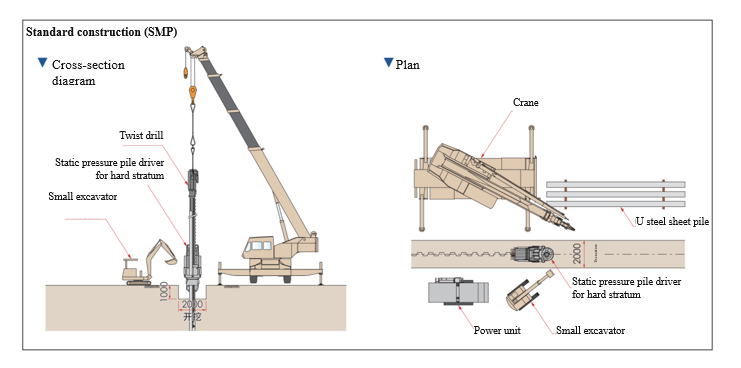
Fig. 7 Composition of staticpressure piling equipment
5.5 Piling Process Test
Before construction, determine relevant piling parameters andspecification of steel sheet pile through process test.
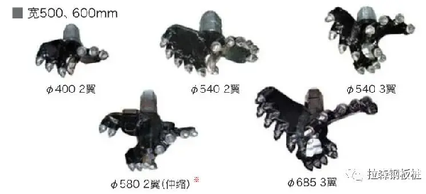
(1) According to geological condition (judgment of complexity ofpre excavation and piling process), the following 3 piling methods can beadopted: Pre- excavate once and erect a pile; pre- excavate once using 685mm bitand erect two consecutive piles; directly erect the pile using 600mm bitwithout pre-excavation.
(2) In the pre- excavation and piling process, drilling slags mayattach to the drill rod easily. As a result, slags cannot be dischargedsmoothly and the construction efficiency will be affected. High pressure air isexhausted via the drill rod center and the drill bit to solve the aboveproblems.
(3) Determine specification of steel sheet pile and adopt SP IIwsteel sheet pile for process test. Due to low strength, the pile body isdamaged in the piling process. The subsequently used SP-IVw steel sheet pile isnot damaged.
5.6 Construction Preparation
5.6.1 Preparation of steel sheet pile construction area and site
When erecting the steel sheet pile using static pressure piledriver, the construction site should be leveled, there should be an at least 3moperation space on both sides of the normal of steel sheet pile, and the floorelevation should be 50cm lower than the top elevation of the steel sheet pile.
5.6.2 Inspection of steel sheet pile
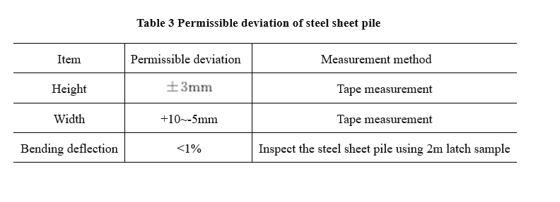
Before erecting the steel sheet pile, carry out completeinspection and remove welding slags of steel sheets and reinforcements afterthe steel sheet pile is used in the early period. The permissible deviation of steel sheet pile is shown inTable 3.
5.6.3 Waterproof treatment of latch of steel sheet pile
To reduce the friction among the latches and the seepage of thesteel sheet pile cofferdam in the piling process, apply butter-asphalt mixtureto the latch (the proportion ratio should be asphalt: butter: talcum powder:saw dust=4: 6: 10: 1).
5.6.4 Preparation of corner pile
4 corner piles of the steel sheet pile cofferdam should belocked and re machined using normal steel sheet in order that the latches canbe mutually engaged, as shown in Fig. 8 and Fig. 9.
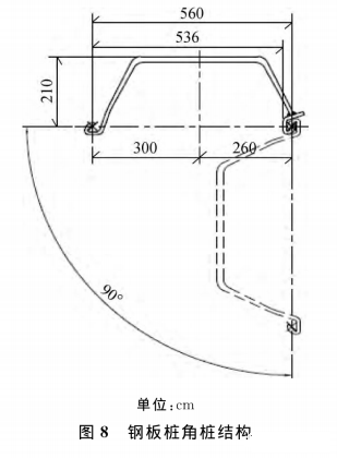
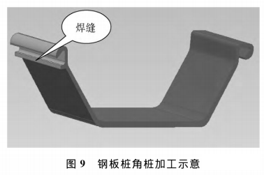
Fig. 9 Corner pilemachining diagram
5.7 Piling construction
5.7.1 Surveying and setting out
(1) Carry out setting out using total station,determine the control point, fix the control point using short bar and mark itusing red paint.
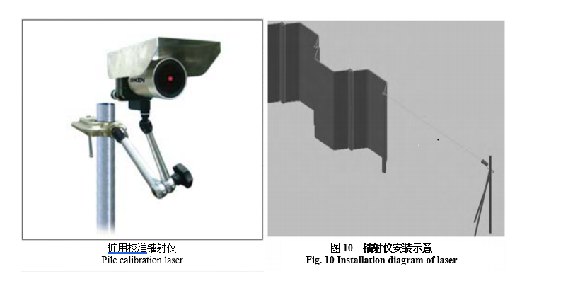
(2) Take out the laser and install it on the measuring point forsetting out.
(3) Adjust the laser in order that the infrared ray produced bythe laser coincides with the planned normal and the elevation of the infraredray is equal to the top elevation of pile, as shown in Fig. 10.
5.7.2 Installation of static pressure piling equipment
The static pressure piling equipment is installed on the counterforce base, the center line of the counter force base is parallel with theplanned normal, the distance from the base to the latch of the first pressedpile should be within 10-20cm. Adjust the deviation in order that the staticpressure pile driver is horizontal, and hoist the balancing weight to bothsides of the counter force base, as shown in Fig. 11.
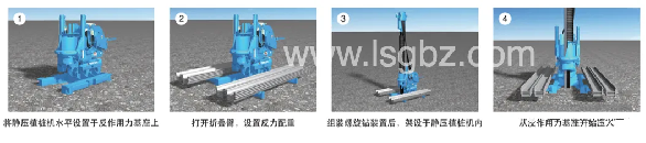
Fig. 11 Equipmentinstallation
The balancing weight can be a precast block or a steel sheetpile.
5.7.3 Pressing in the initial period
Press the first pile using the balancing weight as the counterforce. After that, the pile driver moves forward automatically and grasps thejacked piles successively. When the machinebody is fully located on the counter force pile, remove the counter force baseand the balancing weight to finish pressing in the initial period.
5.7.4 Pre-excavation using twist drill
Determine whether to pre-excavate according to N value andgravel content of stratum.
For stratums with a lot of pebbles and hard for piling,pre- excavate and erect the pile. Pre- excavate using685mm bit, adjust the drill rod according to infrared orientation to ensurepositional accuracy and limit the perpendicularity error of the drill rod to3%, and start pre-excavation. The pre-excavation process contains the following steps.
(1) Installation and positioning of beacon and drilling.
In the pre- excavation process, to avoid damage to the latch ofthe jacked pile caused by the drill bit and better fix the drill bit, installand locate the beacon from the second steel sheet pile.
(2) Monitoring of drill rod position and perpendicularity andhole formation.
In the pre- excavation process, timely observe the position andperpendicularity of the drill rod according to the infrared guide line of thelaser and the horizontal ruler. In case of deflection or skewness (which shouldbe limited to 3%), make adjustments timely to ensure the perpendicularity ofthe pre- excavated hole to the greatest extent. After teaching the design elevation, stop drilling andfinish pre-excavation.
(3) Drilling and rinsing.
Dueto a high clay content of sandy mudstone in this area, the drill rod can easilyattach to clay, which should be removed. A scraper should be installed on thedrill rod before piling. A high pressure water gun should be used to clean thedrill rod in the piling process to keep the drill rod clean.
5.7.5 Formal piling construction
Erect the piles after drilling. The piling process contains the following steps.
(1) Replace the drill bit.
To avoid damage to the latch of the jacked pile caused by thedrill bit, 400mm bit should be used for piling.
(2) Hoist the steel sheet pile.
Manually cooperate with hoisting of steel sheet pile, enable thelimit plate of the welded steel sheet pile locks the drill rod as a whole,clamp the clip and finish hoisting of steel sheet pile.
(3) Adjust the position of the drill rod and erect the piles.
After hoisting of steel sheet pile, tighten the hook of thecrawler crane for auxiliary stabilization, adjust the position in order thatthe latch of the steel sheet pile gets stuck in the latch of the previousjacked pile (only adjust the position in the initial piling process) and thatthe latches are mutually engaged, readjust the position and perpendicularity ofthe drill rod and start piling. Keep the steelsheet pile vertical in the piling process. If the steel sheetpile deflects or inclines, make adjustments timely.
(4) Weld the latch of the steel sheet pile.
Weld the latch of the newly erected steel sheetpile to the latch of the previous jacked pile (to the base in the initialpiling process), with an about 15cm weld, in order that the jacked piles arestressed as a whole and to stabilize the static pressure pile driver.
(5) Erect the corner pile.
Corner pile should be erected at the corner of the steel sheetpile cofferdam using 3 methods according to the direction of the last steelsheet pile on this side, as shown in Fig. 12. Erect the piles in the sequence of ①-⑥, inwhich ③ is corner pile and ⑤ is auxiliary pile.
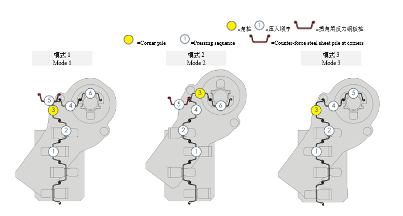
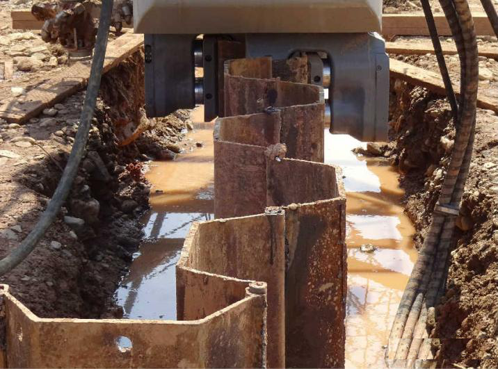
Fig. 12 Corner pile construction diagram
(6) Equipment relocation.
After the corner pile is erected, continue erecting a pile(ordinary steel sheet pile). That is, after the total number of piles on thenext side reaches 2 (for a four leg pile driver, erect another auxiliary pile),hoist them using the crane for the pile driver, locate them on the 2 jackedpiles on the next side and start piling on the next side.
The steel sheet pile should be erected according to the abovesteps until they are closed.
(7) Closure of steel sheet pile.
Where the steel sheet pile will tilt forward slightly duringconstruction, they are often closed in the position of corner pile.
▍6Precautions about Construction and Operation Essentials
(1) In the early construction period of steel sheet pile, carryout analyze or select suitable steel sheet piles according to geologicalcondition. If the steel sheet pile has low strength, it will affect the pilingquality and cause damage; if it has excess strength, it will cause materialwaste and increase the construction cost.
(2) Strictly control the piling accuracy to avoid erroraccumulation; otherwise, the pile body is apt to incline, the piling equipmentcannot be adjusted and the piles cannot be closed normally. excavation process and affecting the waterproof effect of steel sheet pile.
▍7Implementation Effect
7.1 Settlement andDisplacement Observation
After piling, set a settlement and displacement observationpoint around the steel sheet pile and observe the settlement and displacementsituation of all sections.
It can be found from observation that settlement of the steelsheet pile remains unchanged, the maximum displacement variation is 3cm in theearly erection stage, and the displacement tends to be stable after erection.
7.2 Waterproof Effect
After foundation pit excavation, set 2 water collection pitsonly in the cofferdam and discontinuously pump water using 2 sewage pumps tomeet the drainage requirements, as shown in Fig. 13.
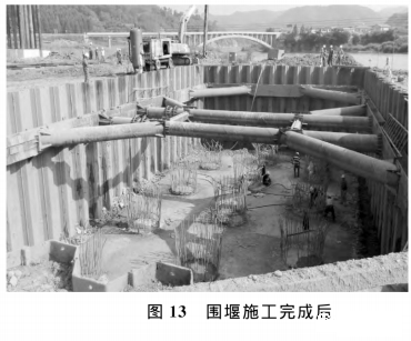
Fig. 13 After completion ofcofferdam construction
▍8Conclusion
The successful application of the static pressure pilingtechnology for the main pier cap of extra-large bridge solved the difficulty insteel sheet pile construction in hard stratum that cannot be solved usingconventional technologies. Meanwhile, the author carried out processoptimization and technological innovation to improve the constructionefficiency, ensure the construction quality, good appearance of steel sheetpile wall and good waterproof effect, and summed up experience to offerreferences to similar projects.
;)
;)